
Research Links
Adapting the White Cell
Adapting the White cell to true time delays: So, what we do is place a MEMS (micro-electro-mechanical systems) micromirror array in the plane of Mirror A, so we can switch beams between different White cells.For true time delays, the White cells are of different lengths. Here is a simple design to illustrate the principle:
Normally, the mirrors on the MEMS are tipped to –10°, and the light bounces back and forth between Mirrors B and C. If a particular pixel is tipped to +10°, then a beam coming from C on that bounce is sent to E. It returns to the exact same next spot as if it had gone to B, but it took longer to get there. If the beam is sent to the long arm twice, it gets a delay of “2” units, the unit being how much longer it takes light to go to E compared to C. We call this the “linear cell” because the number of delays is proportional to the number of bounces.
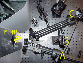
Here is a photograph of the linear cell. This is looking down from the top. We used the Texas Instruments DLP (R) or DMD (R) chip. We bought a computer projector and took it apart! Engineering is great. Read the whole story .
This is the simplest design, but illustrates the general idea. If we add another spherical mirror somewhere, and let half the bounce go to Mirror C above, and the other half go to the new mirror, which is further away, we can have like a 1's place and an "m's" place if we are conting in base m. This is cool becuase now the number of delays goes as (m/2) squared. We have designs that go up to (m/8) to the power of eight, which we call the "octic cell." Polynomial-based optical true-time delay devices with microelectromechanical mirror arrays paper by Betty Lise Anderson and Rashmi Mital.
Adapting the White cell to optical switching:When all you have is a hammer, everything looks like a nail. We can take the same geometry as the time delay device above, but adapt it to switching as follows. First, we make all the arms the same length. Then, we notice that the spot pattern forms in two rows, parallel to the centers of curvature of the spherical mirrors, below on the left. If we "misalign" one of the mirrors, then the spots will form in the wrong row,and the spot comes out in a different place. Every time we visit that misaligned mirror, the spot pattern slips another row. Eventually the beam comes out of the White cell at a new location. The exact location is controlled by how many times we go to the goofy mirror.
Advantages of the White cell approach: The key reason we like the White cell so much is that you can have lots (hundreds or thousands) of light beams bouncing around in there simultaneously, so whether you want to delay them or switch them or whatever, you can do it to a large number of signals with the same hardware: a switch, and a handful of mirrors and lenses. Also, because we use free space (as opposed to fibers or waveguides), the loss is negligible. In the cross-connect, it turns out there that there are many different paths by which a given input can reach a selected output, which in turn means that if some of your swtiches fail, you don't have to replace the switch, just go around the bad ones. This makes the thing reliable.